
Gangaikonda Cholapuram Temple — A Civil Engineering Perspective
Built in 1035 CE by Rajendra Chola I to commemorate his conquest of the Ganges, the Gangaikonda Cholapuram temple stands as one of the most sophisticated masonry structures of the medieval world. This article analyses its foundation system, load paths, masonry mechanics, and hydraulic engineering through a modern structural lens.
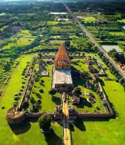
Gangaikonda Cholapuram Brihadeeswara
The vimana (tower) rises 55 m above the sanctum floor — nearly matching its more famous twin at Thanjavur. Built entirely in granite ashlar without mortar, it has stood for nearly 1,000 years in a seismically quiet but cyclone-prone coastal plain.
Gangaikonda Cholapuram ("the city of the Chola who conquered the Ganges") was built between 1025 and 1035 CE as the new Chola capital. Rajendra Chola I commissioned the Brihadeeswara temple as a direct architectural statement — it was designed to equal or surpass the Thanjavur Brihadeeswara (1010 CE) built by his father Rajaraja Chola I.
From an engineering standpoint, the two temples represent a controlled experiment in Dravidian structural design. The Thanjavur tower is a near-vertical shaft; the Gangaikonda Cholapuram vimana has a concave curvature — it tapers inward as it rises, then flares slightly near the top. This subtle geometric difference has profound implications for load distribution and lateral stability.
UNESCO Recognition Both Brihadeeswara temples (Thanjavur and Gangaikonda Cholapuram) are inscribed as part of the "Great Living Chola Temples" UNESCO World Heritage Site (2004). The inscription specifically notes the "remarkable engineering achievement" of the vimana construction.
Ancient builders had no formal structural theory — no Euler buckling equations, no soil bearing capacity formulas, no finite element models. Yet their structures have outlasted most modern reinforced concrete buildings by centuries. Studying them reveals empirical rules that were discovered through trial, failure, and refinement over generations. For a civil engineer, this is a masterclass in structural intuition.
The temple sits on the Cauvery delta plain in present-day Ariyalur district, Tamil Nadu, at an elevation of approximately 75 m above mean sea level. The alluvial plain is underlain by Gondwana formation sedimentary rock at depth, with a surficial layer of medium-dense silty sand and sandy clay — typical of deltaic deposition.
No borehole records exist from the 11th century, but geological surveys of the region and the observed settlement behaviour of the structure allow a reasonable inference:
| Layer | Depth (approx.) | Material | Estimated Bearing Capacity |
|---|---|---|---|
| 1 | 0 – 1.5 m | Topsoil / disturbed fill | — |
| 2 | 1.5 – 4 m | Medium-dense silty sand (SM) | ~100 kPa |
| 3 | 4 – 10 m | Stiff sandy clay (CL) | ~150–200 kPa |
| 4 | 10 – 20 m | Dense gravel / laterite | ~300 kPa |
| 5 | > 20 m | Weathered Gondwana sandstone | > 500 kPa |
Settlement Observation The vimana shows no measurable differential settlement after ~990 years of service. This implies either a very stiff founding stratum or an extremely wide, well-distributed foundation that kept contact pressures well below the bearing capacity of the upper layers. Modern analysis suggests the latter — the Chola builders effectively used a raft-like granite platform to spread the load.
The site falls in IS 1893 Seismic Zone II (low hazard) — peak ground acceleration of approximately 0.10g for a 475-year return period. However, the Bay of Bengal coastline (~200 km east) exposes the structure to cyclonic wind events. The 1977 Andhra Pradesh cyclone (wind speeds ~200 km/h at landfall) passed within 300 km of the site. The temple's survival through multiple such events is a testament to its mass and geometric stability.
The Chola builders used a stepped granite platform (adhisthana) as the foundation system. This is not merely an aesthetic plinth — it is a structural element that performs three engineering functions simultaneously:
- Load spreading: The adhisthana steps outward at each level, distributing the concentrated load from the vimana walls over a progressively larger base area. This reduces contact pressure on the soil.
- Drainage: The stepped profile sheds rainwater away from the base of the structure, preventing saturation of the founding soil and the associated reduction in bearing capacity.
- Lateral confinement: The mass of the adhisthana provides passive resistance against any tendency for the base to slide under lateral wind or seismic loads.
| Element | Plan Dimension | Depth / Height | Material |
|---|---|---|---|
| Adhisthana (top step) | ~30 m × 30 m | ~1.2 m per step | Granite ashlar |
| Adhisthana (base step) | ~40 m × 40 m | ~1.2 m per step | Granite ashlar |
| Sub-foundation platform | ~45 m × 45 m | ~0.6 m | Granite rubble + laterite |
| Total foundation depth | — | ~4–5 m below grade | — |
Using a simplified approach, we can estimate the average contact pressure under the foundation:
Modern Comparison A typical 10-storey RCC building exerts a column load of ~3,000–5,000 kN on a 1.5 m × 1.5 m isolated footing — a contact pressure of ~1,300–2,200 kPa. The Chola foundation, despite carrying a 55 m masonry tower, achieves a far lower contact pressure through its massive spread. This is the ancient equivalent of a raft foundation.
The most remarkable structural feature of Gangaikonda Cholapuram is that the entire vimana — from foundation to the 8-tonne granite capstone (stupi) — is assembled without mortar. The stones are held in place purely by gravity, friction, and geometric interlocking. This is not a limitation of the era; the Chola builders used lime mortar extensively in other construction. The choice of dry-stone assembly was deliberate.
✅ Advantages of Dry-Stone
- No mortar creep or shrinkage cracking over time
- Stones can redistribute loads by micro-movement without cracking
- Thermal expansion accommodated at joints
- Easier to disassemble and reassemble (repair)
- No mortar degradation from moisture cycling
⚠️ Challenges of Dry-Stone
- Requires extremely precise stone dressing (tolerances < 1 mm)
- Tensile capacity is essentially zero
- Lateral loads must be resisted by mass and geometry alone
- Requires careful coursing to prevent progressive collapse
- Capstone placement requires sophisticated lifting equipment
The primary material is Thanjavur granite (a coarse-grained biotite granite), transported from quarries ~80 km south. Modern testing of similar granite from the region gives:
| Property | Value | Relevance |
|---|---|---|
| Uniaxial compressive strength (UCS) | ~180–220 MPa | Extremely high — far exceeds any applied stress |
| Tensile strength | ~8–12 MPa | Irrelevant in dry-stone (joints carry no tension) |
| Elastic modulus | ~60–70 GPa | Stiff — minimal elastic shortening under load |
| Density | ~2,650 kg/m³ | High mass = good lateral stability |
| Coefficient of friction (granite on granite) | ~0.6–0.7 | Critical for joint shear resistance |
| Water absorption | < 0.5% | Excellent durability in wet climate |
In a dry-stone joint, the only mechanism resisting horizontal sliding is friction. The shear capacity of a horizontal joint can be estimated using the Coulomb friction model:
Interlocking Geometry The Chola masons used lewis holes (tapered mortise cuts) and tongue-and-groove joints at critical locations — particularly at the base of the vimana and at the capstone. These mechanical interlocks provide additional shear resistance beyond friction alone, and were the ancient equivalent of shear keys in modern precast concrete construction.
The most critical compressive stress occurs at the base of the vimana walls, where the full weight of the tower is concentrated:
Understanding how loads travel through the Gangaikonda Cholapuram vimana requires recognising that Dravidian temple architecture is fundamentally a compression-only structure. Every design decision — the tapering profile, the thick walls, the concave curvature — serves to keep all resultant forces within the middle third of each cross-section, ensuring no tensile stress develops anywhere in the masonry.
- Capstone (stupi): The 8-tonne granite finial sits atop the vimana. Its weight is transferred to the top course of the tower through direct bearing.
- Vimana wall courses: Each successive course of granite blocks transfers load to the course below through direct compression. The concave taper means the wall cross-section increases as you descend — compressive stress remains roughly constant despite increasing load.
- Garbhagriha walls: The thick walls of the sanctum (estimated 3–4 m thick at base) act as the primary load-bearing element. The hollow interior (the sanctum itself) is structurally analogous to a hollow box section — efficient in bending resistance.
- Adhisthana: The stepped plinth spreads the concentrated wall loads over the full foundation area before transferring to the soil.
The inward-curving profile of the Gangaikonda Cholapuram vimana (as opposed to the straight taper of Thanjavur) is not merely aesthetic. It has a specific structural consequence: the resultant of the self-weight vector and the horizontal wind force is directed more steeply inward at each level, keeping it within the kern of the cross-section more reliably than a straight taper would.
The vimana resists lateral wind and seismic loads through three mechanisms, in order of contribution:
| Load Case | Overturning Moment (est.) | Stabilising Moment (est.) | Factor of Safety |
|---|---|---|---|
| Design wind (IS 875 Zone 3, V = 50 m/s) | ~120,000 kN·m | ~1,800,000 kN·m | ~15 |
| Extreme wind (cyclone, V = 70 m/s) | ~235,000 kN·m | ~1,800,000 kN·m | ~7.7 |
| Seismic (Zone II, PGA = 0.10g) | ~90,000 kN·m | ~1,800,000 kN·m | ~20 |
Why Such High Safety Factors? The Chola builders had no way to calculate these values. Their "safety factor" was the accumulated empirical knowledge of generations of temple builders — they built what they knew worked, and what they knew worked was massive, wide-based, and tapering. The result, by modern analysis, is a structure with safety factors that would be considered excessive by today's standards — but which have delivered ~1,000 years of reliable service.
The Gangaikonda Cholapuram complex is inseparable from its water infrastructure. Rajendra Chola I commissioned the Chola Gangam — a massive artificial irrigation tank — as an integral part of the capital city project. The tank was not merely a ceremonial feature; it was a sophisticated hydraulic system that served agricultural, civic, and ritual functions simultaneously.
According to inscriptions, Rajendra Chola I ordered water from the Ganges (carried in pots by defeated kings) to be mixed into the tank — a symbolic act that gave the city its name. The engineering reality behind this legend is a reservoir of approximately 16 km² surface area, fed by a network of channels drawing from the Kollidam (Coleroon) river.
The Chola Gangam embankment is an earthen dam — a compacted earth bund with a masonry-faced spillway. The design principles align closely with what modern geotechnical engineering would prescribe for a low-head earthen dam:
| Feature | Chola Gangam Design | Modern Equivalent |
|---|---|---|
| Embankment material | Compacted black cotton soil (expansive clay) with laterite core | Zoned earthfill dam — clay core, granular shell |
| Upstream face | Stone-pitched slope (rubble masonry) | Riprap or concrete face protection |
| Downstream face | Grassed slope, ~1V:2H | Grassed or riprap slope, typically 1V:2.5H |
| Spillway | Masonry weir with cut-stone sill | Ogee or broad-crested weir |
| Sluice (surplus outlet) | Stone-lined tunnel with timber gate | Conduit with slide gate or radial gate |
| Freeboard | ~1.5 m above design flood level | IS 11223 recommends 1.0–1.5 m for small dams |
The tank fed a network of gravity-flow irrigation channels (kulams and odais) that distributed water to paddy fields across the Cauvery delta. The hydraulic design of these channels demonstrates a sophisticated understanding of open-channel flow principles — centuries before Chezy (1775) or Manning (1889) formalised the equations.
The tank's outlet sluice is a particularly impressive piece of hydraulic engineering. A stone-lined conduit passes through the embankment base, controlled by a timber slide gate seated against a dressed granite frame. The hydraulic head across the gate could reach 6–8 m at full tank level.
Integrated Water Management The Chola Gangam tank was not an isolated feature — it was part of a cascade tank system where overflow from one tank fed the next downstream. This redundancy meant that a failure of any single embankment would not cause catastrophic downstream flooding. Modern dam safety engineers call this a "series reservoir system" and it is considered best practice for small dam networks in flat terrain.
Within the temple complex, a smaller pushkarini (ritual bathing tank) was fed by a dedicated channel from the Chola Gangam. The pushkarini is lined with dressed granite steps (ghats) on all four sides — a structural detail that also serves as a retaining wall for the embankment around the tank. The step geometry (typically 300 mm tread, 150 mm riser) is remarkably close to modern stair design standards.
Building a 55 m granite tower in 1035 CE — without steel, without Portland cement, without motorised equipment — required solving a set of engineering and logistics problems that would challenge a modern contractor. The Chola builders solved them with a combination of large-scale organisation, ingenious mechanical advantage, and meticulous quality control.
The granite was quarried from outcrops near Thanjavur, approximately 80 km south of the construction site. The quarrying technique used thermal spalling (heating the rock face with fire, then quenching with water to induce fracture along natural joints) combined with iron wedges driven into pre-cut channels.
| Operation | Method | Modern Equivalent |
|---|---|---|
| Rock splitting | Fire + water thermal shock; iron wedge-and-feather | Diamond wire saw; hydraulic splitter |
| Stone dressing | Iron chisels, abrasive sand lapping for flat faces | CNC stone cutting; surface grinding |
| Transport (quarry to river) | Timber sledges on greased wooden rails; elephant haulage | Flatbed truck; rail transport |
| River transport | Timber rafts on the Kollidam river (seasonal) | Barge transport |
| Site transport | Timber rollers; ox-drawn sledges on compacted earth ramps | Mobile crane; forklift |
| Vertical lifting | Earthen ramps (inclined planes); rope-and-pulley systems | Tower crane; hydraulic lift |
The most debated aspect of Chola construction is how the upper courses of the vimana were placed. The most widely accepted theory is a spiralling earthen ramp that wound around the growing tower, allowing ox-teams to haul stone blocks to progressively greater heights.
The Capstone Problem The 8-tonne granite stupi (finial) at the apex of the vimana is a single monolithic piece. Placing it at 55 m height — with millimetre precision onto the top course — is perhaps the most impressive single feat of the entire construction. Some researchers propose a vertical lifting frame (a timber gin pole with rope-and-pulley) rather than a ramp for the final capstone placement. The mechanical advantage required: 8 tonnes ÷ (4 pulleys × 2 rope runs) = ~1 tonne per hauling team — achievable with 20–25 men.
For dry-stone masonry to function structurally, the bearing faces of each stone must be flat to within approximately 1 mm over 300 mm — a flatness tolerance of 1:300. This was achieved by:
- Rough dressing at the quarry using iron chisels — removes bulk material, achieves ±5 mm flatness.
- Fine dressing at the site yard using finer chisels and abrasive rubbing stones — achieves ±2 mm flatness.
- Lapping of mating faces together with abrasive sand between them — achieves the final ±1 mm contact fit. This is the ancient equivalent of surface grinding.
- Trial assembly of each course on the ground before lifting — ensures fit before the stone is at height.
| Trade | Estimated Workers | Role |
|---|---|---|
| Stone quarriers | ~2,000 | Extraction, rough splitting at quarry |
| Stone dressers (silpis) | ~3,000 | Fine dressing, carving, lapping |
| Transport labourers | ~1,500 | Sledge hauling, raft operation, site logistics |
| Ramp builders / earthworkers | ~1,000 | Ramp construction, maintenance, removal |
| Masons (stone setters) | ~500 | Placing and aligning courses on the tower |
| Supervisors / engineers (sthapatis) | ~50 | Design, layout, quality control |
| Total (peak) | ~8,000–10,000 | Over a ~10-year construction period |
The Gangaikonda Cholapuram temple is not merely a historical curiosity — it is a working proof-of-concept for several structural and geotechnical principles that modern engineers apply daily. Here are the key lessons, translated into contemporary engineering language:
The entire vimana is a compression-only structure. Every geometric decision — the tapering profile, the thick walls, the concave curvature — exists to keep all resultant forces within the kern of each cross-section. Modern unreinforced masonry design (IS 1905, BS 5628, Eurocode 6) is built on exactly this principle. The Chola builders discovered it empirically; we now have the mathematics to prove why it works.
IS 1905 Connection IS 1905:1987 (Code of Practice for Structural Use of Unreinforced Masonry) requires that the resultant of all forces at any section of a masonry wall fall within the middle third of the section — identical to the kern condition the Chola builders satisfied intuitively. See the IS Codes directory for the full IS 1905 reference.
The adhisthana demonstrates that the correct response to a heavy concentrated load on moderate soil is to spread the load over a large area — not to use a stronger material. This is the raft foundation principle. Modern geotechnical design (IS 6403 for bearing capacity, IS 1904 for foundation design) formalises this with the Terzaghi bearing capacity equation, but the underlying logic is identical.
Granite with <0.5% water absorption, zero mortar joints that cannot degrade, and a surface that sheds water — the Chola builders selected their material for durability first, strength second. Modern durability design (IS 456 exposure categories, ACI 318 w/c ratio limits) follows the same hierarchy: a structure that lasts is more valuable than one that is merely strong.
The overturning safety factors of 7–20 against wind and seismic loads are far beyond what modern codes require (typically 1.5–2.0). This "over-design" is not waste — it is robustness against unforeseen loads. The temple has survived events (cyclones, minor earthquakes, foundation settlement) that were never explicitly designed for. Modern structural engineering increasingly recognises this through concepts like structural robustness (IS 875 Part 3, Eurocode 1 Annex A) and disproportionate collapse prevention.
The temple, the Chola Gangam tank, the channel network, and the city were designed as a single integrated system. Water management was not an afterthought — it was a co-equal design objective alongside the structural tower. Modern civil engineering increasingly recognises this through integrated urban water management and green infrastructure frameworks. The Chola capital was, in modern terminology, a water-sensitive urban design project.
| Chola Engineering Principle | Modern Code / Standard | Key Parameter |
|---|---|---|
| Kern condition (no tension in masonry) | IS 1905:1987, Eurocode 6 | e ≤ b/6 |
| Raft-like foundation spreading | IS 1904:1986, IS 6403:1981 | q ≤ q_allowable |
| Friction-based joint shear | IS 1905, BS 5628 Cl. 27 | V ≤ μN |
| Overturning stability | IS 875 Part 3, IS 1893 | FOS ≥ 1.5 |
| Earthen dam embankment | IS 8826:1978, IS 11223:1985 | Freeboard, slope stability |
| Gravity irrigation channel | IS 7112:1973 (canal design) | Manning's n, V/V_critical |
| Durability (low water absorption) | IS 456:2000 Table 5 | w/c ≤ 0.45 (severe exposure) |
The two Brihadeeswara temples — built 25 years apart by father and son — are the closest thing ancient India produced to a controlled structural experiment. Same material, same construction tradition, same religious programme, but measurably different geometry. The differences reveal deliberate engineering choices, not stylistic variation.
| Parameter | Thanjavur Brihadeeswara (1010 CE) | Gangaikonda Cholapuram (1035 CE) | Engineering Implication |
|---|---|---|---|
| Vimana height | ~66 m | ~55 m | Thanjavur is taller; GKC trades height for geometric stability |
| Vimana profile | Near-vertical straight taper | Concave inward curve | GKC profile keeps resultant deeper within kern under lateral load |
| Base plan | ~30 m × 30 m | ~30 m × 30 m | Similar base — height-to-base ratio differs (2.2 vs 1.8) |
| Height-to-base ratio | ~2.2 | ~1.8 | GKC is proportionally squatter — higher overturning FOS |
| Capstone (stupi) mass | ~80 tonnes (single block) | ~8 tonnes | Thanjavur capstone is 10× heavier — a more extreme lifting challenge |
| Garbhagriha wall thickness | ~3.7 m | ~3.0–3.5 m | Both use thick-wall box section for vimana support |
| Mortar use | None (dry-stone) | None (dry-stone) | Identical — pure friction and gravity jointing |
| Foundation type | Stepped granite adhisthana | Stepped granite adhisthana | Identical system — proven at Thanjavur, replicated at GKC |
| Associated water body | Sivaganga tank (~2 km²) | Chola Gangam (~16 km²) | GKC tank is 8× larger — more ambitious hydraulic engineering |
| Structural survival | ~1,016 years, intact | ~991 years, intact | Both validate the structural system over ~1,000-year service life |
The Concave Profile — A Deliberate Refinement? Structural historians debate whether the concave vimana profile at Gangaikonda Cholapuram was a conscious engineering improvement over Thanjavur's straight taper, or a purely aesthetic choice. The structural analysis supports the former: the concave profile demonstrably improves kern compliance under lateral loads. Given that Rajendra Chola I's engineers had 25 years of observing the Thanjavur tower under wind and monsoon loads, a deliberate refinement is the more plausible explanation.
The two temples together demonstrate that the Chola engineering tradition was iterative and self-correcting — not static. The builders observed, measured (implicitly), and refined. This is the essence of engineering practice, whether in 1035 CE or today. The concave profile, the larger tank, the refined adhisthana proportions — all point to a tradition that learned from its own work.